English 

Views: 0 Author: Site Editor Publish Time: 2026-05-01 Origin: Site


Selecting the right display technology is rarely just about visual aesthetics. It operates as a critical system-level architectural decision. Design teams face a difficult balancing act during early prototyping phases. Over-specifying a display inflates Bill of Materials (BOM) costs and heavily burdens microcontroller (MCU) resources. On the other hand, under-specifying degrades the final user experience and severely limits essential product functionality. Solving this tension requires true hardware insight. This guide moves beyond basic definitions to unpack the actual engineering demands. We will explore the firmware complexities, memory requirements, and commercial realities behind these technologies. You will learn exactly how to evaluate and integrate a Segment LCD, an alphanumeric module, or a high-resolution dot-matrix panel into your next product line.
Segment LCDs offer the lowest power consumption and per-unit cost for battery-operated devices, but require fixed, factory-tooled UI layouts.
Character LCDs provide a balanced, highly legible alphanumeric interface with near-zero MCU RAM overhead by utilizing built-in Character Generator ROMs (CGROM).
Graphic LCDs deliver maximum UI flexibility (multi-language fonts, complex curves, dynamic icons) but demand significantly higher MCU memory (RAM/Flash) and longer firmware development cycles.
Choosing a display involves a direct and unavoidable trade-off. You must constantly balance UI capability against system resource allocation. Engineers evaluate visual requirements against harsh hardware constraints. Displays do not function as simple plug-and-play devices. Screen complexity directly dictates processing speed requirements. It also demands RAM for buffering and Flash memory for storing visual assets.
We often see projects stumble due to the MCU bottleneck. High-resolution screens require massive data throughput. Fonts and bitmaps consume vast memory blocks. Failing to align the display type and MCU architecture causes severe issues. It frequently forces late-stage hardware revisions. You might need to upgrade the MCU. This action immediately increases the BOM. Alternatively, you might cut UI features. This compromise harms product marketability.
Moving pixels takes time. If your MCU uses all its cycles updating the screen, it cannot process sensor data or handle wireless communication. Advanced systems use Direct Memory Access (DMA) to bypass the CPU. This allows background screen refreshes. However, adding DMA usually forces you into a more expensive microcontroller tier.
Common Mistake: Many teams select a panel based solely on mechanical fit or initial visual appeal. They ignore the underlying firmware and memory requirements until the prototyping phase.
Best Practice: Always draft a strict memory budget. Calculate the exact RAM and Flash footprint required by your visual interface before finalizing the host controller.
Engineers often call these "static" or "break code" displays. These panels rely on fixed glass etching. Manufacturers permanently cut the UI into the glass. They use a physical grinding tool during production. This layout never changes after manufacturing. The driving mechanism utilizes multiplexing. This time-division scanning significantly reduces required I/O pins. The host controller benefits immensely from this simplified interface.
These panels construct images using Indium Tin Oxide (ITO) traces deposited on glass substrates. A twisted nematic fluid responds to the electric field. You must drive them with an alternating current waveform. Driving them with direct current destroys the fluid rapidly. They offer unmatched ultra-low power consumption. They run effortlessly on coin-cell battery devices for years. Smart meters and digital thermostats rely heavily on them.
Designers often integrate reflective or transflective polarizers to enhance outdoor visibility. They provide extremely high contrast and sunlight readability. Furthermore, they achieve a rock-bottom unit price at high production volumes.
However, serious adoption risks exist. You have absolutely zero layout flexibility post-manufacturing. Custom icons and layouts require upfront Non-Recurring Engineering (NRE) tooling fees. These fees make them cost-prohibitive for low-volume, agile prototyping. They serve specific, high-volume needs perfectly, but they punish rapid design iterations.
Multiplexing benefit: Reduces pin count on the host MCU drastically.
Power draw: Often measures in single-digit microamps (µA).
Visibility: Excels in direct sunlight environments without backlight power.
Manufacturers design these screens specifically for fixed-grid text. They use common 16x2 or 20x4 layouts. These displays utilize discrete blocks of 5x8 or 5x10 pixel matrices. Physical gaps exist between characters. An onboard controller handles all the heavy lifting. The HD44780 standard represents a classic industry framework. The module contains a built-in dictionary of glyphs. We call this a Character Generator ROM (CGROM). It also includes dedicated Display RAM (DDRAM).
The host MCU only needs to send simple ASCII hex codes. You can transmit these over a parallel or I2C bus. System RAM overhead drops to practically zero. This efficiency allows low-end 8-bit microcontrollers to easily drive the interface. You skip the complex mathematical operations required for rendering pixels entirely.
Engineers often leverage Character Generator RAM (CGRAM). This small memory block allows you to design up to eight custom 5x8 pixel icons at runtime. You can create custom battery life indicators, signal strength bars, or specific scientific symbols. This feature adds a touch of customization without massive memory overhead.
Adoption risks center around visual rigidity. Rigid formatting completely prevents modern, fluid UI designs. Multi-language support remains severely limited beyond the factory-burned ROM. You often need clunky workarounds to display foreign characters. You might even require a custom ROM mask. Despite these limits, a Character LCD serves industrial applications exceptionally well.
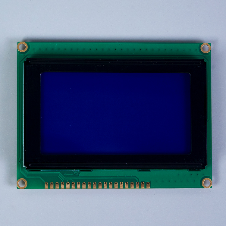
Unlike the discrete blocks of alphanumeric screens, these panels use a tight dot-matrix grid. Tiny 0.02mm gaps separate the continuous pixels. You gain arbitrary pixel control. This renders custom vectors, multi-language typography, and dynamic charts effortlessly. Pixels map directly to memory addresses. Updating the screen requires complex "read-modify-write" operations. The MCU executes these across specific page and column sectors.
Implementation risks heavily impact MCU overhead. We must carefully evaluate three primary constraints:
The RAM Tax: Smooth drawing requires a Frame Buffer. A standard 128x64 Graphic LCD requires at least 1KB of dedicated RAM. This demand can immediately exhaust entry-level microcontrollers.
Flash Memory Drain: Vectoring custom fonts consumes massive storage. Storing bitmap images requires significant Flash upgrades. You often need external storage chips to hold complex UI assets.
Firmware Complexity: Graphical GUIs demand weeks of software development. Engineers use specialized graphics libraries. In contrast, simpler screens take only hours to program.
Modern development relies heavily on open-source graphics libraries like LVGL or uGFX. While these libraries provide beautiful buttons and sliders, porting them to your specific hardware requires deep C-programming expertise. You must write custom display drivers and touch controller interfaces. The debugging process often consumes significant project bandwidth.
Unit price gradients vary widely across different technologies. At scales of 1k-5k units, a standard 16x2 screen hovers around two dollars. A basic 128x64 graphical panel starts significantly higher. Packaging architecture dictates the final BOM structure and mechanical design.
Chip-on-Board (COB) mounts the controller on a PCB behind the glass. It measures physically thicker but proves highly durable. It provides easy mounting holes. This setup saves valuable mechanical design time. Chip-on-Glass (COG) bonds the IC directly to the glass ledge. The display arrives much cheaper and thinner. However, it transfers engineering burdens directly to the buyer. You must engineer custom PCB routing. You handle FPC connectors and mechanical housing.
Operating temperature ranges also impact the BOM heavily. Industrial environments require wide-temperature fluids and specialized polarizing films. Standard consumer-grade panels freeze or turn entirely black at extreme temperatures. Upgrading to an automotive-grade or industrial-grade panel often doubles the base unit cost.
Hidden costs accumulate quickly. A graphical interface requires an upgraded host processor. It demands expanded Flash memory. Extended engineering hours further increase the overall investment required to launch the product.
System Resource and Feature Comparison Table
Display Type | MCU RAM Required | UI Flexibility | Typical Interface |
|---|---|---|---|
Static Custom Glass | Extremely Low | None (Fixed Layout) | Multiplexed Pins |
Alphanumeric Panel | Near Zero | Low (Grid Bound) | Parallel / I2C |
Dot-Matrix Array | High (Buffer Needed) | Maximum (Arbitrary) | SPI / Parallel |
Making the final call requires strict logic. You must align your product goals with hardware realities. Use the following framework to shortlist the correct technology for your next build.
Display Selection Summary Chart
Use Case Scenario | Recommended Display | Primary Technical Reason |
|---|---|---|
Battery-powered medical meter | Static etched glass | Sub-microamp power draw extends battery life |
Industrial HVAC server panel | Alphanumeric module | Zero RAM tax, instant text rendering |
Smart home thermostat with graphs | Dot-matrix panel | Real-time arbitrary pixel plotting capability |
Choose a custom etched panel when the device runs strictly on batteries. Portable medical meters and smart thermostats fit this perfectly. You display a fixed set of metrics. The product will scale to high volumes, easily justifying initial tooling costs.
Choose an alphanumeric array when the system relies on a constrained 8-bit MCU. The primary function involves simple data logging. Server racks and industrial panels use them often. Rapid firmware deployment remains your top priority over visual flair.
Choose a dot-matrix panel when the product requires an intuitive interface. You need real-time data visualization like graphs or waveforms. The design requires robust multi-language localization. Your hardware budget easily accommodates a robust MCU with adequate memory.
Successful integration acts as a strict exercise in resource management. Do not select a screen based solely on visual appeal. You must audit the host microcontroller thoroughly. Check its available RAM carefully. Evaluate Flash capabilities and data bus speeds. Ensure the MCU can fully support the specific driver principles of the chosen technology.
Take actionable steps before locking in your hardware architecture. First, prototype your UI using software emulators. Second, calculate the exact memory footprint of your desired font libraries. Finally, test data transfer speeds over your chosen SPI or I2C bus to guarantee flicker-free performance. Solid engineering upfront prevents expensive hardware redesigns later.
A: Yes. You can program a graphical panel to display basic text. However, doing so requires the MCU to calculate and push every individual pixel to the screen. You do not get the RAM-saving benefits of a true hardware CGROM. The processor handles all the heavy lifting.
A: Unlike dot-matrix screens that use generic grids, static panels require custom glass etching. Manufacturers create proprietary masks to form your specific icons and number layouts. This physical customization demands upfront engineering and manufacturing fees before mass production begins.
A: I2C works excellently for simple alphanumeric drivers where pin count must be minimized. It handles low data speeds perfectly. For graphical screens where full-screen pixel buffers transfer frequently, SPI is highly recommended to prevent noticeable rendering lag and screen tearing.


