English 

Views: 0 Author: Site Editor Publish Time: 2026-05-26 Origin: Site


While high-resolution graphical displays dominate modern consumer electronics, industrial and commercial hardware rely heavily on the humble text display. These reliable units offer proven longevity, incredibly low power draw, and highly standardized integration. For hardware product managers and engineers at the crucial decision stage, selecting the right display requires careful balance. You must carefully weigh bill-of-materials (BOM) costs against microcontroller (MCU) resource constraints and overall environmental durability. A wrong choice often leads to frustrating board redesigns or severely delayed product launches. Understanding the underlying memory architecture, initialization requirements, and physical display modes of a Character LCD is absolutely critical. This foundational knowledge allows you to evaluate suppliers effectively. It ensures a seamless hardware rollout. We will explore how these displays function at the hardware level. You will learn the exact interfacing protocols needed to prevent screen corruption. Finally, we cover essential procurement strategies to secure a robust, long-term component supply chain.
Standardized Reliability: Most Character LCDs utilize the industry-standard HD44780 controller, ensuring high supply chain interchangeability.
Low Compute Overhead: Built-in memory (CGROM/CGRAM) offloads character rendering from the host microcontroller.
Environmental Adaptability: Choosing between positive and negative polarization modes determines readability across diverse lighting conditions.
Strategic Procurement: Evaluating a Character LCD manufacturer requires assessing Chip-on-Board (COB) quality, MOQ thresholds, and long-term availability.
Hardware engineering teams constantly face restrictive component budgets and tight power consumption limits. These alphanumeric text modules deliver exceptional value for enterprise and commercial applications. They provide a predictable, reliable interface without the massive overhead required by modern touchscreens.
The electronics industry heavily standardizes the 14-pin and 16-pin interface connections used by these display modules. Physical form factors, like the ubiquitous 16x2 or 20x4 character arrays, remain remarkably consistent across different brands globally. Swapping suppliers during a severe component shortage poses minimal engineering risk. You avoid the complex printed circuit board (PCB) redesigns usually required for proprietary graphical displays. This interchangeability protects your manufacturing timeline.
Displaying text on these modules requires sending simple hexadecimal commands. You do not need to push massive, continuous pixel arrays over high-speed buses. This efficiency allows you to use cheaper, lower-power microcontrollers in your core design. System memory and CPU cycles remain completely free for critical sensor monitoring or real-time motor control tasks. Furthermore, the modules consume mere milliamps of current, significantly extending battery life in portable hardware.
Industrial deployment environments demand exceptionally rugged components. Most text-based display modules use Chip-on-Board (COB) manufacturing techniques. Thick, black epoxy resin fully encapsulates and protects the delicate controller IC directly on the PCB. This robust construction makes them highly suitable for harsh operating conditions. They excel in heavy industrial machinery, portable medical devices, and outdoor HVAC interfaces. They handle mechanical shock much better than fragile glass-on-glass designs.
You achieve the lowest possible cost-per-unit for simple alphanumeric data readouts. Hardware teams avoid over-engineering the user interface for utility-focused devices. Users get clear, immediate information without unnecessary graphical clutter. The simplicity of a Character LCD ensures higher user comprehension in fast-paced industrial environments.
Understanding the internal mechanics helps developers write highly optimized firmware. It also prevents common communication errors during the prototyping phase. The internal architecture delegates visual rendering tasks away from your main processor.
Nearly all text-based LCDs use the Hitachi HD44780 controller or a functionally identical clone. It serves as the underlying visual processing engine. This specific IC dictates the strict initialization sequence, the exact hex instruction set, and vital timing limits. Adhering strictly to this standard ensures your firmware code works perfectly across multiple display vendors.
These displays utilize three distinct, specialized memory blocks to manage visual output on the screen:
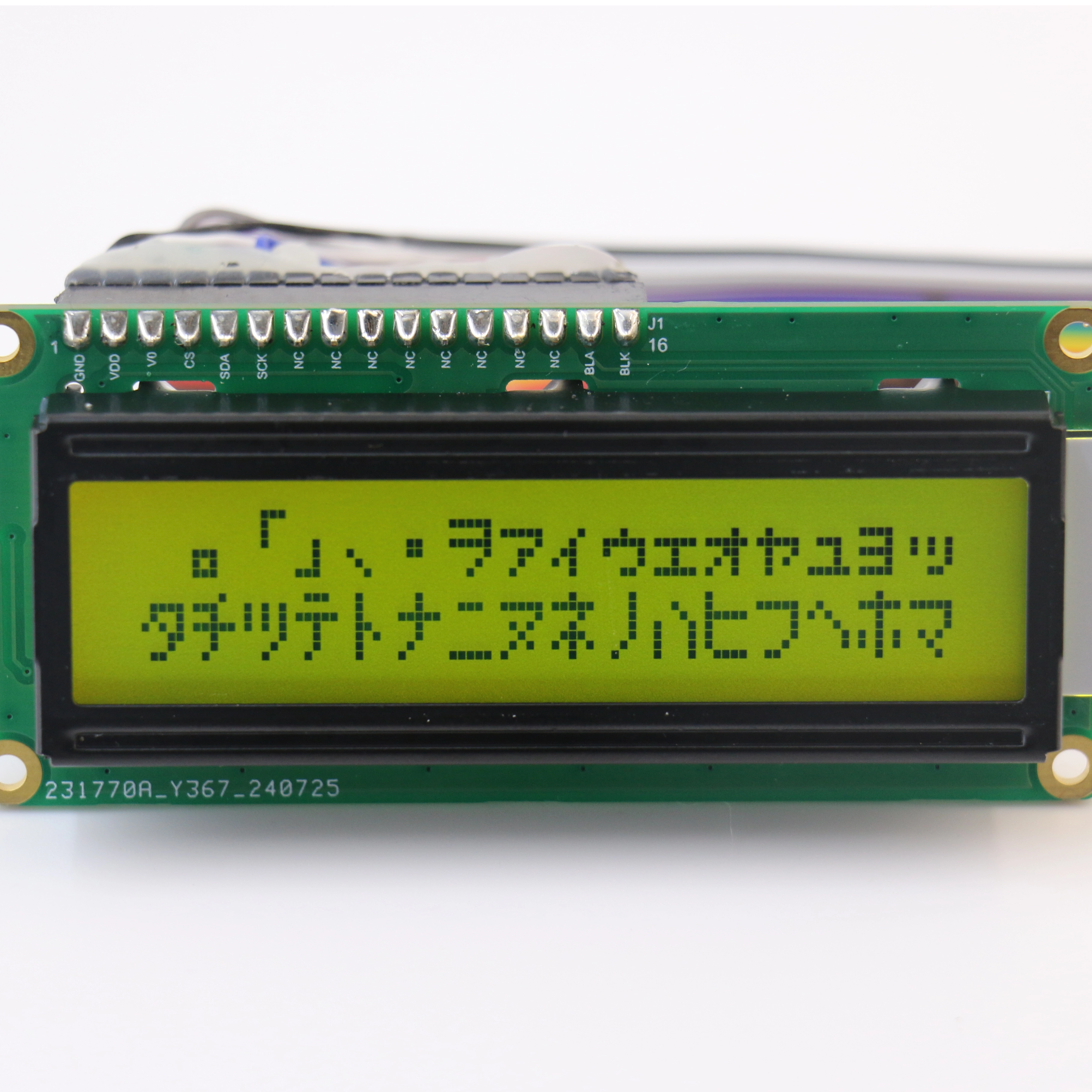
CGROM (Character Generator ROM): This hardcoded factory library contains all standard ASCII characters. It also holds specific regional alphabets like Japanese Kana. These characters map precisely to 5x8 or 6x8 pixel grids. Since it is ROM, you cannot modify these native fonts.
DDRAM (Data Display RAM): This spatial memory maps specific text characters to their physical coordinates on the glass screen. It typically contains 80 bytes of storage. Interestingly, the memory addresses are often non-contiguous. Moving a cursor from the end of row one to the start of row two requires specific jump commands.
CGRAM (Character Generator RAM): This highly volatile memory area allows developers to define custom symbols. You can create up to 8 unique icons, like dynamic battery meters or specific foreign characters. You build them by sending raw binary arrays directly to the controller memory.
Microcontrollers send data to the display via an 8-bit or 4-bit parallel data bus. Modern hardware designs highly favor the 4-bit mode. This method requires sending each byte of data in two separate nibbles (four bits at a time). While it takes slightly more code, it successfully saves four valuable General Purpose Input/Output (GPIO) pins on the host microcontroller. You can repurpose those saved pins for extra sensors or user buttons.
Selecting the correct physical display traits ensures optimal visibility for the end user. You must match the physical screen attributes to its final operating environment. A display meant for a dark server room will fail entirely in direct sunlight.
The physical arrangement of polarizer layers dramatically changes the visual output of the module.
Positive Displays: These units feature a light background paired with dark, opaque text. Manufacturers achieve this by using perpendicular polarizing filters. They are ideal for bright, ambient light environments like outdoor gas pumps or factory floors. They require very minimal LED backlight power, making them great for battery-operated tools.
Negative Displays: These units feature a dark background displaying brightly lit text. They use parallel polarizing filters. They perform best in low-light or strictly indoor environments. Server racks, audio equipment, and aircraft cockpits often use them. A strong LED backlight provides the sharp, readable contrast required.
The chemical liquid crystal fluid injected between the glass panes dictates the viewing angle and overall contrast ratio.
Fluid Technology | Visual Contrast | Viewing Angle | Ideal Application Use Case |
|---|---|---|---|
TN (Twisted Nematic) | Basic, adequate contrast | Narrow (direct view mostly) | Low-cost basic consumer electronics, stationary desk devices |
STN (Super Twisted Nematic) | Higher contrast, slight color tint | Wider (visible from sides) | Industrial machine panels requiring multi-angle visibility |
FSTN (Film-Compensated STN) | Excellent, very sharp monochrome | Extremely Wide | High-end medical devices mounted at extreme ergonomic angles |
Integrating these screens seems straightforward initially, but specific pitfalls trap many junior engineers. Strict adherence to official timing datasheets prevents frustrating screen lockups and unpredictable behavior.
Hardware self-initialization in these display modules is notoriously imperfect. Relying purely on the automatic power-on reset circuit often leaves the screen completely blank. If the power supply voltage rises too slowly, the internal reset fails. Engineers must hardcode a strict initialization sequence into their firmware. You send specific hexadecimal commands, such as 0x30 followed by 0x38, multiple times. You must carefully program precise millisecond delays between these early commands. This rigorous process guarantees the controller wakes up reliably every single time the device turns on.
The embedded HD44780 controller operates much slower than modern 32-bit ARM microcontrollers. Blindly pushing data down the bus causes immediate screen corruption. You might see random foreign characters or strange blinking cursors appear. The microcontroller must pause momentarily and wait for the screen to fully process each received byte. Ignoring these critical timing windows is the most common reason for a non-functioning display.
Many basic tutorials rely on inefficient, hardcoded software delay loops to handle timing. This basic approach wastes thousands of valuable CPU cycles. Enterprise-grade firmware handles communication differently. It actively reads the display's internal "Busy Flag" by polling the R/W (Read/Write) pin. The MCU checks the most significant bit (MSB) of the returned data. This technique explicitly verifies the controller is completely ready for the next instruction. It heavily optimizes data write speeds without ever crashing the display.
Securing a reliable hardware partner guarantees long-term product success. You need a trusted supplier capable of maintaining consistent manufacturing quality across multiple, multi-year production runs. Price alone should never drive your final procurement decision.
A reputable Character LCD manufacturer prioritizes highly robust physical construction. They will utilize high-grade epoxies for their Chip-on-Board encapsulation process. This black resin dome must fully seal the bare silicon die to prevent oxidation. Precision-machined metal bezels also matter immensely. High-quality bezels compress the elastomeric zebra connectors perfectly evenly. This prevents dead pixel rows from appearing after a device experiences drop shocks. It also acts as a strong physical barrier against external moisture ingress.
Evaluate if the supplier supports cost-effective physical modifications. Many industrial projects require custom LED backlight colors to match corporate branding. You might also need extended temperature range fluids. Standard TN fluids typically freeze near 0°C, rendering them useless outdoors. You might need specialized fluids operating smoothly from -20°C to +70°C. Ask if they can modify specific pinout headers or wire harnesses directly at the factory. A great partner handles these custom requests without charging exorbitant Non-Recurring Engineering (NRE) setup fees.
For B2B hardware deployment, supply chain continuity is vital. Unexpected component obsolescence forces expensive, time-consuming hardware revisions. Shortlist suppliers offering highly flexible Minimum Order Quantities (MOQs) tailored to your scale. Furthermore, they must explicitly guarantee multi-year production lifecycles. Standard 16x2 and 20x4 alphanumeric modules should remain available for at least five to ten years to support your entire product lifecycle.
Bringing a new hardware device to market requires deeply practical component choices.
Final Verdict: Character LCDs remain the absolute most pragmatic choice for text-critical hardware applications. They seamlessly balance BOM cost, immense power efficiency, and incredible environmental resilience perfectly.
Next Steps: Procurement and engineering teams should align strictly on core environmental requirements first. Decide on the specific fluid type and polarization before reviewing parts.
Map out your main microcontroller's pin constraints early. This determines if you should utilize 4-bit or 8-bit parallel communication modes.
Finally, request detailed technical datasheets and physical evaluation samples from a thoroughly vetted manufacturer. Test your initialization sequence code on a breadboard before committing to a final PCB layout.
A: Only to a very limited extent. You can create up to 8 custom 5x8 pixel blocks using the CGRAM. This feature is useful for drawing simple battery icons, signal bars, or specific symbols. However, for full-screen graphics or large logos, a Graphic LCD or TFT display is required.
A: The 4-bit mode frees up 4 critical data pins on the microcontroller. You can use these saved pins for extra sensors or outputs. It requires two separate write cycles per character, but this is a completely negligible speed tradeoff for text displays.
A: This is the classic symptom of a failed initialization sequence or an incorrectly adjusted contrast potentiometer (V0 pin). The firmware must adhere strictly to the controller's datasheet timings. Ensure your initial boot-up millisecond delays are long enough to properly wake the IC.


