
English 
Views: 0 Author: Site Editor Publish Time: 2026-10-12 Origin: Site


Hardware engineers and procurement teams consistently face a critical bottleneck when specifying display components. You must carefully balance strict form factor requirements against upfront tooling expenses and long-term durability. This delicate balancing act often dictates product launch timelines. The choice between a COG vs COB LCD directly impacts your device's final thickness and weight. Furthermore, it determines the expected failure rate in harsh operating environments and the unit economics of mass production. Making the wrong choice can lead to costly redesigns or field failures. This article provides a comprehensive, evidence-oriented evaluation framework. You will discover how to confidently select the right display technology for your specific application. We break down physical constraints, supply chain scalability, and hardware lifecycle demands to streamline your engineering decisions.
Space & Footprint: COG modules offer significant space savings and ultra-thin profiles by mounting the IC directly to the glass, eliminating the bulky PCB required by COB.
Durability & Environment: COB modules excel in high-vibration and rugged industrial environments due to the protective epoxy resin over the IC and secure PCB mounting.
Cost Dynamics: COB is highly cost-effective for low-volume or legacy projects with zero-to-low NRE (Non-Recurring Engineering) costs, whereas COG becomes more economical at scale despite higher initial custom tooling fees.
Sourcing Reality: Partnering with an experienced LCD module manufacturer early in the design phase is critical to navigating MOQ (Minimum Order Quantity) constraints and compliance requirements for both technologies.
To make an informed engineering decision, we first need to understand the architectural foundation of both display technologies. The physical structure dictates how the module behaves under stress and how it integrates into your final product housing.
The COB architecture relies on robust, legacy manufacturing principles. In this setup, the display controller integrated circuit (IC) is wire-bonded directly onto a rigid printed circuit board (PCB). Manufacturers use extremely fine gold or aluminum wires to establish this electrical connection. Once bonded, they seal the sensitive IC under a "glob top." This glob top consists of a hard, protective epoxy resin that shields the silicon die from moisture and physical impacts.
In terms of component reality, a chip on board LCD requires substantial bezel space. The mechanical design must completely hide the PCB connections. It must also conceal necessary mounting holes and the rigid backlight structure. This inherently prevents ultra-sleek device designs.
The COG architecture represents modern, high-density display integration. Here, the display controller IC bonds directly to the Indium Tin Oxide (ITO) glass substrate. Manufacturers use Anisotropic Conductive Film (ACF) to achieve this bond. ACF provides simultaneous electrical conductivity and mechanical adhesion under high heat and pressure.
In terms of component reality, a chip on glass LCD eliminates the primary controller PCB entirely. Instead of a rigid board, it relies on a Flexible Printed Circuit (FPC). The FPC routes signals from the glass substrate down to your main system motherboard.
You must evaluate your assembly line capabilities carefully. The two technologies demand completely different manufacturing and handling setups.
FPC Handling for COG: Your assembly line must handle fragile flex cables without inducing stress. COG integration requires precise automated alignment tools. Bending the FPC too sharply can sever the delicate traces.
Connection Robustness for COB: COB provides traditional pin-out headers. It can also utilize standard ribbon cables. These interfaces tolerate manual assembly and hand-soldering much better.
Tooling Capital: Upgrading a production line to bond COG flex cables demands significant capital investment. Conversely, COB slots easily into older, established PCB assembly workflows.
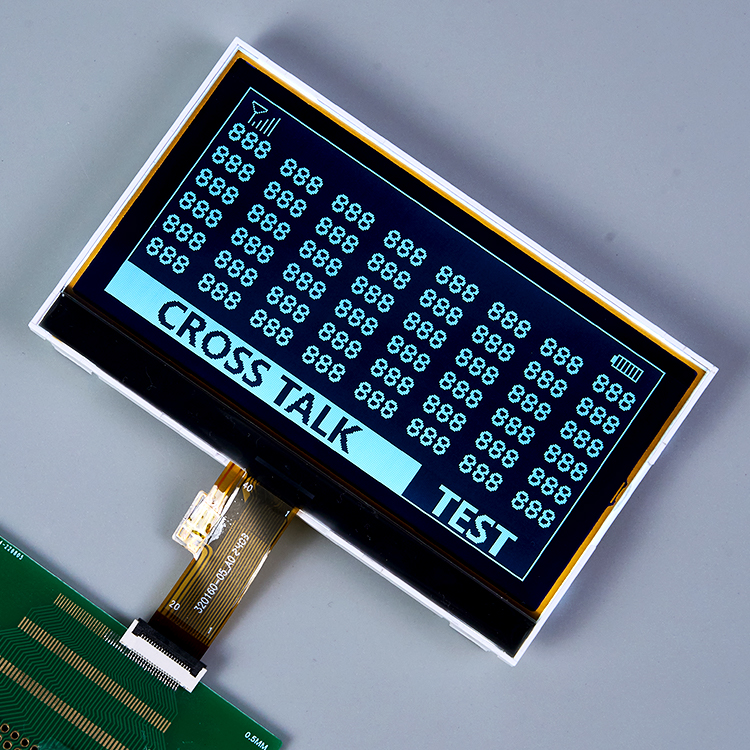
Modern product design often prioritizes extreme compactness. Every millimeter matters when laying out an internal device chassis. The display module usually dictates the minimum acceptable depth of your product enclosure.
Device thickness strongly influences modern consumer appeal. A COG LCD module drastically reduces overall Z-axis height. The complete removal of the controller PCB makes the unit exceptionally thin. In many cases, COG modules are more than 50% thinner than their legacy counterparts. If you are designing a wearable device, this Z-axis reduction is strictly mandatory.
COG technology also allows for significant X/Y footprint reduction. It enables "borderless" or minimal-bezel designs. By moving the IC onto the viewing glass, you eliminate the need for wide borders. This feature remains critical for consumer wearables, smart home thermostats, and modern handheld medical scanners. It maximizes the active display area without increasing the overall device dimensions.
You must acknowledge the physical trade-offs. A COB LCD module inherently requires a larger footprint. The rigid PCB dictates the absolute minimum physical dimensions. You must accommodate corner mounting holes. You also need space for the bulky backlight housing and the protruding epoxy glob top. This forces a thicker, wider product design overall.
To avoid costly housing redesigns, hardware teams should watch out for these common sizing mistakes:
Ignoring the required FPC bending radius when calculating COG enclosure depth.
Failing to account for the epoxy glob top height variance on COB modules.
Underestimating the bezel width needed to hide COB mounting hardware entirely.
Spatial Constraints Decision Matrix
Constraint Type | COG Capability | COB Capability | Recommended Choice |
|---|---|---|---|
Z-Axis Depth < 5mm | Excellent (Ultra-thin profile) | Poor (PCB adds thickness) | COG |
Minimal Bezel Design | Excellent (No PCB borders) | Poor (Requires wide borders) | COG |
Ample Internal Space | Adequate | Excellent (Easy mounting) | COB |
If your product housing is strictly constrained, COG is the only viable path. If internal space is ample, COB remains a highly reliable fallback.
A display must survive the environment it operates in. Industrial factory floors present entirely different challenges than climate-controlled living rooms. You must match the module's physical resilience to your target environment.
COB offers much stronger resistance to heavy vibrations and mechanical shock. The epoxy-coated IC acts as a robust physical buffer. The rigid PCB provides a stable foundation that resists flexing. Heavy vibrations do not easily dislodge the internal components. These factors make it ideal for heavy machinery, automotive instrument clusters, and ruggedized military gear.
Conversely, COG modules demand careful handling. The glass edges remain inherently fragile. They can chip or shatter easily upon side impact. You must design careful housing enclosures. We recommend using shock-absorbing gaskets around the display perimeter. Furthermore, you must ensure stress-free FPC routing. Any tension transferred from the mainboard to the glass can cause micro-cracking, resulting in instant pixel failure.
Heat dissipation behaves differently across the two architectures. COB dissipates heat efficiently through the PCB structure. The internal copper layers act as highly effective heat spreaders. They pull thermal energy away from the sensitive controller IC.
COG relies entirely on the thin glass substrate for cooling. Glass conducts heat poorly. You must perform precise thermal profiling during the prototyping phase. Extreme environments demand rigorous heat testing for COG designs, as localized hot spots can degrade the liquid crystals.
Both module types must pass strict temperature cycling protocols. Both undergo intense humidity tests. However, COB generally maintains a wider baseline tolerance for uncontrolled environments. It survives harsh outdoor deployments reliably out of the box. You can use COG outdoors, but it usually requires specific ruggedization processes.
Implement these best practices to ensure long-term durability:
Use compression gaskets around COG edges to prevent impact damage.
Apply conformal coating to COB boards if deployed in high-moisture or corrosive environments.
Secure the FPC on COG modules using adhesive tape to eliminate vibration fatigue.
Engineering decisions ultimately intersect with budget constraints. You must carefully analyze the unit economics across the entire project lifecycle, from initial prototyping to mass production.
COB relies on standardized, abundant tooling setups. The Non-Recurring Engineering (NRE) costs remain remarkably low. This cost dynamic makes it highly favorable for prototyping phases and pilot runs. Low-MOQ batches (such as 500 to 1,000 units) benefit heavily from this structure. You can validate your market without sinking capital into custom glass masks.
COG requires high precision custom glass cutting. The ACF bonding tools carry high setup fees. Therefore, you face higher upfront NRE charges. However, the per-unit material cost drops rapidly at scale. The elimination of the PCB and simplified material bill make it highly efficient. When producing high volumes (over 10,000 units), COG becomes highly economical despite the initial setup fees.
Sometimes you need a custom LCD module to fit a unique enclosure design. Modifying a COB board is generally cheaper and much faster. It usually only requires a standard PCB layout revision, which most engineers can execute swiftly. Conversely, re-spinning a COG design requires a brand new glass mask. This delays your schedule significantly and increases engineering fees.
Component availability should heavily influence your design choice. COG technology aligns perfectly with modern high-density IC manufacturing. Silicon foundries prioritize these newer architectures for consumer electronics. Therefore, modern COG controllers benefit from strong, stable supply chains.
Meanwhile, some legacy COB controllers face severe end-of-life (EOL) risks. Older controller chips eventually cease production as fabs upgrade their nodes. You must verify long-term silicon availability with your supplier before committing to a legacy COB architecture for a new product.
Matching the technology to the end-user application prevents over-engineering and reduces field failure rates. Use this matrix to guide your selection process.
Winner: COG. Devices like smartwatches, fitness trackers, and sleek smart home hubs demand extreme compactness. COG delivers the absolute minimum weight and thickness required. The aesthetic demand for narrow bezels makes COG the only logical choice in this vertical.
Winner: COB. Factory floors and construction sites destroy fragile components. Engineers here prioritize impact resistance above all else. Easy mounting via standard PCB holes and long-term hardware longevity trump sleek aesthetics. CNC machines, forklifts, and factory automation panels rely heavily on COB.
Context Dependent. This category requires careful evaluation. Handheld diagnostic tools and portable field monitors lean toward COG for superior portability and weight reduction. Conversely, stationary hospital equipment, such as bedside patient monitors and laboratory analyzers, often utilizes COB. The robust nature and cost-efficiency make COB ideal for large, stationary chassis designs.
We urge engineers to define their exact dimensional limits early in the design process. You must determine your required environmental ratings, such as IP (Ingress Protection) or IK (Impact Protection) codes. Establish your target production volume to understand your scaling economics. After defining these parameters, contact an experienced LCD module manufacturer. Engage them early in the hardware design phase before requesting formal quotes to ensure accurate pricing and feasibility.
The COG vs COB LCD debate is not about one technology being universally superior. It is a strict engineering trade-off between sleek form factor capabilities and rugged cost-efficiency. You must weigh the aesthetic benefits against physical reliability and manufacturing budgets. Choose COG to optimize for space, reduce weight, and lower the mass-production unit cost. Choose COB to optimize for physical durability, simplify internal mounting, and minimize upfront tooling fees for low-volume runs. We strongly advise readers to consult with an engineering-led display manufacturer. Review your native CAD files together and run a specific NRE versus unit price break-even analysis. This collaborative approach ensures your hardware aligns perfectly with your commercial goals.
A: COG usually demands higher MOQs. This is due to the automated ACF bonding setup required. The specialized glass cutting process also makes small runs economically unviable. Conversely, COB can easily accommodate smaller batches. The standardized PCB manufacturing process makes low-volume production highly accessible.
A: Yes, COB modules are highly stable in extreme environments. The epoxy coating protects internal connections well. However, you must specify wide-temperature liquid crystal fluids during the design phase. This prevents the display from freezing or turning black under severe weather conditions.
A: COF serves as a middle ground. The IC mounts directly onto a flexible ribbon rather than the glass or a rigid board. This architecture offers high flexibility and allows for ultra-narrow bezels. However, it comes at a premium production cost compared to standard modules.
A: Industry standards dictate that NRE fees are often rebated. This usually happens after your project hits specific mass production volume thresholds. You should negotiate these rebate terms with your manufacturing partner during the initial quoting phase to lower long-term expenses.


