English 

Views: 0 Author: Site Editor Publish Time: 2026-05-05 Origin: Site


OLED and TFT displays often grab consumer headlines today. Despite this, simple glass displays remain the true industry standard. Hardware teams rely on them heavily. They power critical medical devices, rugged industrial meters, and smart home appliances. These applications demand high reliability. They also require long lifecycles and ultra-low power consumption. Complex displays often fail in these specific areas.
Selecting the right custom display involves a complex balancing act. You must weigh BOM costs against environmental durability. Power constraints and visual branding also play critical roles. A slight miscalculation can lead to excessive battery drain. It might also cause poor readability in harsh sunlight.
This article provides a clear, evidence-based framework. We built it for hardware teams and procurement managers. You will learn how these components work. We will show you how to evaluate, design, and source them reliably. Our goal is to help you build better products.
Drive Logic Requires AC: Segment LCDs must be driven by alternating voltage (VRMS); prolonged DC voltage causes permanent electrochemical damage to the liquid crystals.
Tech Matches the Tier: TN/HTN dominates low-power battery devices, while VA (Vertical Alignment) delivers premium, high-contrast aesthetics for plugged-in hardware.
DFM Prevents Failures: Strict adherence to segment gap limits (≥0.20mm) and line widths (≥0.15mm) during the drawing phase eliminates 80% of production defects.
Supplier Selection: Partnering with a specialized Segment LCD manufacturer requires evaluating their long-lifecycle support, not just the initial tooling quote.
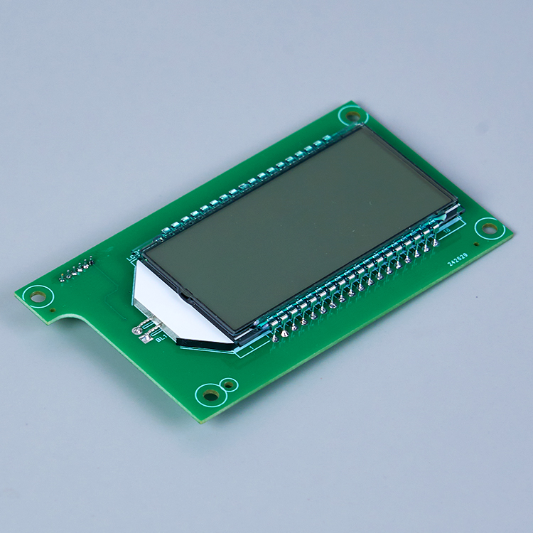
Engineers often use different terms to describe these displays. Industry terminology includes static displays, 7-segment displays, or glass-only displays. They operate using a passive matrix approach. Active-matrix TFTs control every pixel independently via thin-film transistors. Passive matrix relies on intersecting transparent conductive lines. This makes them inherently simpler and more robust.
The fundamental stack resembles a precise optical sandwich. Light travels through several specific layers. The assembly begins under a top polarizer. A front glass piece sits below it. Next comes the ITO (Indium Tin Oxide) conductive layout. This transparent layer shapes the actual icons. Nematic liquid crystal fluid fills the microscopic gap. A rear glass piece seals the fluid safely inside. Finally, a bottom polarizer or reflector finishes the structural stack.
Liquid crystals respond uniquely to electrical fields. However, they require strict driving rules to survive long-term.
The "No DC" Rule: Liquid crystals degrade quickly under Direct Current (DC). Voltages exceeding 50mV cause permanent electrochemical damage. They require AC waveforms to shift light polarization safely. System drivers use charge pumps and bias voltages for this specific purpose.
Static (Direct) Drive vs. Multiplexed (Muxed): You can drive the glass using two main methods.
Static Drive: This method uses 1-to-1 pin control. Each visual segment gets its own dedicated pin. It delivers maximum contrast. It also provides superior extreme-cold temperature performance. This happens because it lacks a duty cycle.
Muxed Drive: This approach shares COM and SEG pins. It drastically reduces MCU pin-out requirements. However, it requires precise bias voltage management. You must tune it carefully to maintain crisp contrast.
Choosing the right fluid material dictates visual performance. Different technologies serve very different user experiences. You must match the fluid to your target environment.
These represent the most common entry-level fluids. They offer the fastest optical response times. They also provide the lowest cost. Contrast remains standard but highly functional.
They do have physical limitations. Viewing angles are typically narrow. They range from 45° to 65°. Grayscale inversion can occur off-axis. Colors may look inverted if viewed from extreme angles.
They work best for utilitarian battery-powered devices. Calculators and basic thermostats use them perfectly. These tools assume fixed, head-on viewing angles.
STN fluid provides much wider viewing angles. It twists the liquid crystal molecules further. However, STN naturally carries a yellow-green or blue tint. FSTN solves this inherent color issue.
FSTN adds a specialized compensation film. This film neutralizes the internal color shift. It creates a sharp black-and-white visual experience. FSTN panels are ideal for industrial equipment. They offer wider off-axis readability. They achieve this without creating a massive cost spike.
VA represents the premium tier of passive displays. The liquid crystal molecules align vertically. They block light completely when turned off. This creates a "dead-front" deep true-black background. Contrast levels are exceptionally high.
VA does have one major limitation. It requires a continuous LED backlight to function. You cannot use it in a purely reflective, unlit mode.
VA is best for premium home appliances. Automotive dashboards and medical devices use them frequently. Perceived brand value and sharp aesthetics matter deeply in these markets.
Technology Type | Viewing Angle | Visual Appearance | Ideal Application |
|---|---|---|---|
TN / HTN | Narrow (45°–65°) | Basic black on gray/green | Battery-operated, low-cost tools |
STN / FSTN | Wide | Sharp black & white (FSTN) | Industrial meters, factory panels |
VA / UWVD | Ultra-Wide | Deep true-black, dead-front | Premium appliances, medical tech |
Hardware teams must balance many variables during design. Use this five-step framework to narrow your options logically. It prevents costly redesigns later.
The ambient light determines your polarizer requirement. You have three primary choices.
Full Dark/Indoor: Choose a transmissive polarizer. This mode requires a continuous backlight to remain visible.
Direct Sunlight/Outdoor: Choose a reflective polarizer. It utilizes ambient light to illuminate the screen. It needs zero backlight power.
Mixed Lighting: Choose a transflective polarizer. This combines ambient reflection during the day and a subtle backlight for low-light conditions.
Determine the physical mounting position early. A wall thermostat viewed from below needs a 6 o'clock viewing angle optimization. A tabletop meter viewed from above needs a 12 o'clock angle. The manufacturing process optimizes the glass for one primary viewing direction.
Energy budgets dictate fluid choices heavily. Suppose your device runs on a coin-cell battery for five years. You must restrict your selection to reflective TN or HTN displays. These panels draw mere microamps. They consume practically zero power because they lack a backlight.
Evaluate your target retail price and brand identity. Can the overall product budget support the premium look of a VA panel? VA provides stunning aesthetics. If you simply need functional readability, a standard FSTN often meets the user requirement perfectly.
Your MCU dictates how you talk to the glass. You must decide between three primary control methods.
MCU Software Bit Banging: This approach manipulates pins directly. It is CPU-heavy and generally not recommended.
Dedicated Internal MCU LCD Driver: Some microcontrollers feature built-in hardware controllers. This is highly efficient and saves board space.
External Driver ICs: You can add a dedicated external chip. It communicates via SPI or I2C. This frees up MCU resources entirely.
Quality issues often arise before manufacturing even begins. Up to 80% of custom display defects stem from poorly engineered layout drawings. Light leaks, ghosting, and disjointed visuals are completely preventable.
Precision is everything in ITO layout design. You must respect electrical boundaries.
Minimum Line Width: Never drop your line width below 0.15mm. We strongly recommend 0.18mm or larger. Thin lines cause broken visual segments and poor overall contrast.
Segment Gap (Spacing): Maintain a gap of at least 0.20mm between active zones. Gaps falling under this threshold cause voltage bleed. This bleed creates noticeable ghosting. Conversely, overly wide gaps make icons look disconnected and unnatural.
Do not treat custom glass like a high-resolution pixel grid. Avoid using complex PC fonts. You should design minimalist hardware icons instead. Scale the segment size strictly to the end-user's viewing distance. Handheld medical devices require tuning for 20 to 30 centimeters. Factory floor panels must remain legible from 70 to 100 centimeters away.
Protect the top polarizer based on the usage environment. Specify exact top-layer treatments to your vendor. A 3H Anti-Scratch coating works well for heavy physical handling. Add an AG (Anti-Glare) treatment if the screen faces harsh overhead lighting.
Navigating quotes requires understanding the underlying hardware constraints.
Several physical factors dictate the final unit price. The overall glass dimensions set the baseline cost. The number of connection pins drives ITO routing complexity. Specialized polarizers add marginal costs. Finally, backlight integration changes the price significantly. A simple Chip-on-Board (COB) setup differs drastically from a sleek Chip-on-Glass (COG) assembly.
Custom setups carry an initial tooling fee. This NRE charge covers custom glass masks and cutting dies. However, custom designs offer an exceptionally low per-unit cost at scale. You achieve the best return on investment at volumes exceeding 10,000 units annually.
Avoid vendors who push unnecessary active-matrix technology. You want a partner who respects your power limits. A reliable Segment LCD manufacturer will proactively audit your DFM. They will verify operating temperature ranges carefully. For example, industrial units need -20°C to 70°C limits verified. They also guarantee long-term component availability. This dedication prevents costly forced redesigns later. Selecting the right Segment LCD depends entirely on partnering with a team focused on hardware longevity.
These simple glass panels are far from a legacy technology. They represent a highly engineered solution for hardware stability. They deliver unmatched cost-efficiency and low power consumption. To move forward successfully, keep these final action steps in mind.
Finalize your environmental requirements first. Lock in your lighting, viewing angle, and power limits before drawing anything.
Strictly follow DFM spacing rules. Use 0.20mm gaps to prevent ghosting.
Partner with a focused vendor early. Do this before requesting an engineering drawing or prototype.
A: Not always. A highly customized, oversized static panel using advanced VA materials can cost more per unit. Complex glass cuts and dense pinouts add to this price. Meanwhile, mass-produced, standard-sized TFT modules often hit very aggressive price points due to sheer consumer volume.
A: Ghosting usually stems from DC voltage drift. This happens when the driver generates an improper AC waveform. It can also occur if you set the bias voltage too high for your chosen multiplex rate. Both scenarios cause adjacent inactive segments to leak light.
A: Yes. Standard nematic fluid slows down visibly in extreme cold. However, you can specify a wide-temperature fluid mix. Combining this robust fluid with a Static (Direct) drive method ensures fast, reliable operation even in freezing environments.


